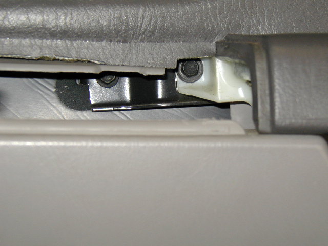
Photo 1
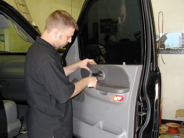
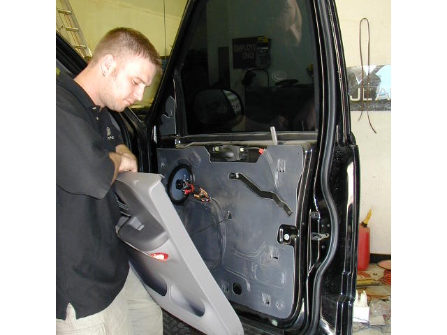
The first photo shows removal of the inner door handle shroud. This piece is snapped into place or held with a single screw so remove with care so the tabs don't break.
Notice that the window is in the up position.
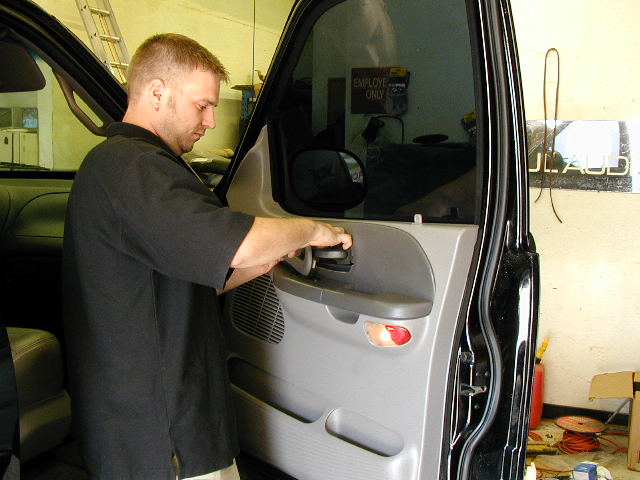 Photo 1
 Photo 2
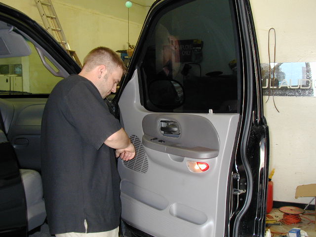
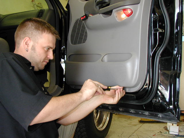
Preparing to remove the electric window/door lock switch panel ahead of the arm rest. This is held in place with some snap clips so carefully pry the module straight up off the door.
 2
2 Photo 3
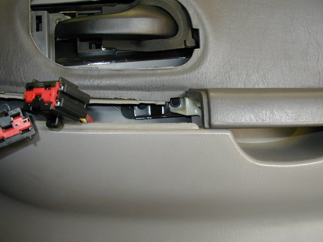
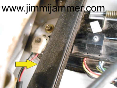
Disconnect the wires at the connector. Be careful since some connectors lock into the connected position. Look for the release tab if the connectors are hard to get apart.
Near the center of the photo you can see a bolt head in the switch module cavity. This is one of the screws or bolts holding the panel onto the door. Remove this bolt.
The next photo, #4 shows a close up of the bolt to remove.
 3
3 Photo 4
Remove the bolt to the right on this photo.
 4
4 Photo 5
Shows removal of the screws holding the panel in place. Look along the edge of the panel, there are several screws, especially along the bottom edge.
 5
5 Photo 6
With panel screws all removed, carefully lift the door panel up and away from the door, but only a few inches. You will need to disconnect the courtesy lamp wire before moving the panel more than a few inches.
 6
6Photo 7
Carefully disconnect the courtesy lamp before moving the door panel away from the door.
 7
7 Photo 8
Check that no other wires are connected to the panel, then pull the panel away from the door.
 8
8 Photo 9
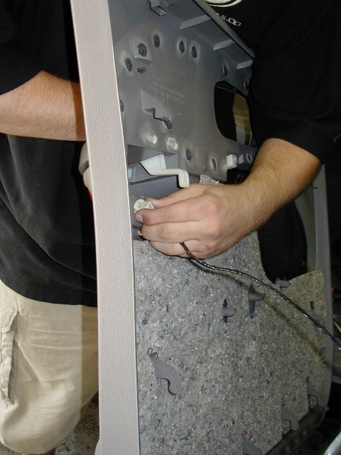
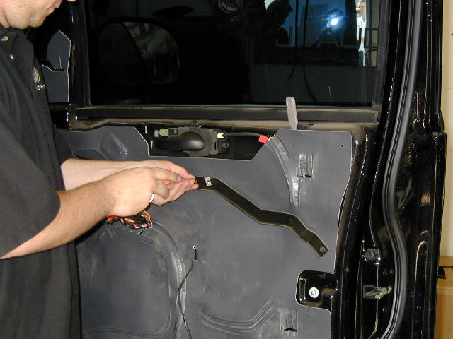
Once the panel is removed, take off the bar holding the splash guard in place. Don't lose the two screws holding it on.
 9
9 Photo 10
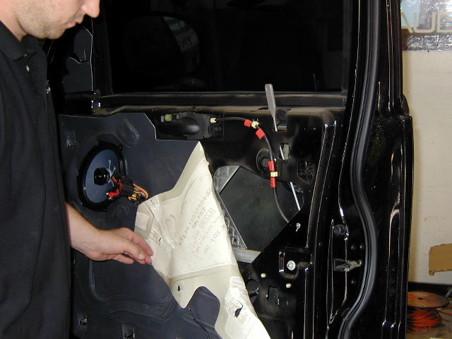
Gently peel back the splash guard to expose the opening to the door cavity. If there is adhesive holding the splash guard in place, it is usually reusable type. Try to peel the guard back carefully to keep as much adhesive on it as possible.
 10
10
Photo 11 - Driver side door view
This photo shows the lower window channel still in place. To free up additional work space inside the door, remove the lower window channel.
See photos 12, 12a and 12b below. It only takes a minute and will give you allot more room to work.
 11 (Drivers side shown here)
Removal of the lower window channel. (Easy).
Make sure the window is all the way up.
Photo 12a: Remove the bolt holding the lower window channel in place at the bottom of the channel.
There is a clip on the top end that holds the lower channel to the upper channel. Feel or look inside the door to see how the clip joins the two together before taking them apart.
With bolt removed, pull lower channel straight down until the upper clip slides off the upper channel.
Photo 12b shows the clip on the top end of the lower channel after it has been disjoined from the upper channel.
Photo 12c shows pulling the lower channel out of the door.
Now you will have extra room to work inside the door.
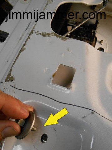 Photo 12a
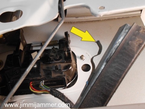 Photo 12b
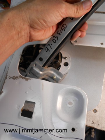 Photo 12c
At this point in the tutorial, we will start showing more photos of the driver side door. There are a few differences between sides so we will try to show as much detail as possible.
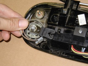
Next, remove the lock rod from the pawl (white plastic piece) OR remove the lock pawl from the lock and leave the rod in the pawl. Either way is ok.
To remove the rod from the pawl:
Use a long nose pliers to squeeze the top or bottom tab on the pawl while applying force on the lock rod toward the pawl opening. Apply constant force on the rod and alternate pinching the pawl clips until the rod pops out.
Another trick, if you're having trouble releasing the rod from the pawl, is to use a screwdriver shaft about the same size as the lock rod and put the shaft into the lock pawl open end.
Then, push the shaft toward the lock rod until they touch, then pull both the rod and screwdriver shaft out at the same time.
OR
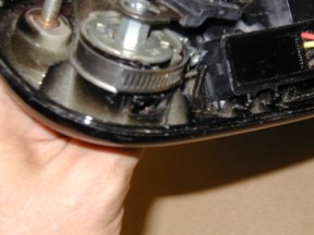
Leave the rod in the pawl and take the lock pawl off the lock. Here's how to do that::
Place a towel or large rag below the handle to catch the c-clip if you drop it down into the door cavity.
Use a short screwdriver to slide the c-clip off the lock. It usually comes off pretty easy.
Then, lift the lock pawl off the lock. This will make plate installation quite easy.
Also in this step, remove the two nuts holding the door handle to the door metal. Photo 13a shows both nuts along the top of the handle.
If you are working on the drivers door, read the next section about the Ford Anti-Theft Rotary Switch in the next section now.
 13a (Passenger side)
 13b (Driver side)
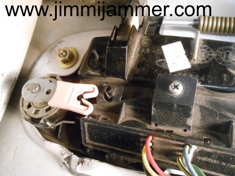
Ford's Anti-theft Switch
If you don't see this switch on your lock cylinder, you can skip this part. The lock pawl has been removed for clarity.
Some vehicles may be equipped with Ford's Anti-Theft switch. Photo 14a shows how this switch mounts to the back of the lock cylinder.
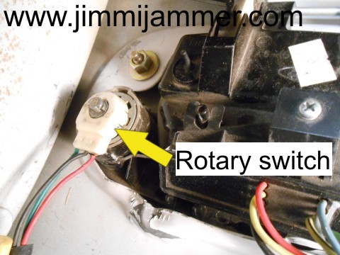
If your vehicle is equipped with this switch, there are a couple of things to be aware of before moving it.
The main thing is to NOT rotate the inner portion of the switch with relation to the outer portion while handling the switch.
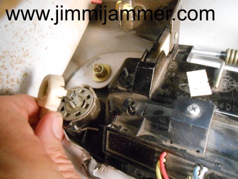
You can lift the switch straight off the lock without issue, just don't rotate the inner portion and make sure you put it back on in the same orientation as it was. See Photo 14b.
Not all vehicles are equipped with this switch, but if it is there, just use care in handling.
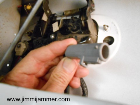
You can also disconnect the switch at the connector end and leave the rotary portion on the lock. This will allow you to feed the wire though the hole on the Jimmi Jammer plate for mounting. Photo 14c.
 14a
14a
 14b
14b
 14c
14c
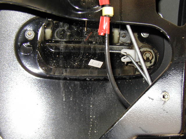
Photos 15a and 15b
These photos were taken outside the door for clarity, but you should be able to get them on without removing the door handle. It is worth the effort to put these on!
With the lock pawl and rod out of the way, put the provided circular clamp around the lock cylinder holder.
This helps strengthen the assembly making it much more difficult to punch the lock into the door or otherwise break the lock holder.
Photo 15a shows the clamp being put onto lock holder.
Photo 15b shows the clamp placed properly. Note that clamp butts up against the lock cylinder holder clip.
This greatly increases the strength of this assembly.
Photo 15b, clamp around lock holder
|
|---|
Photos 16a, 16b and 16c
Photo 16a shows the Jimmi' Jammer® plate installed on the drivers side handle. This vehicle did not have the Ford Anti Theft Rotary switch.
Photo 16b shows the Jimmi' Jammer® plate installed on the drivers side handle WITH the Anti Theft Rotary switch. Note the wires are on this side of the plate.
To position the plate, it helps to have both nuts off the handle mounting studs and to pull the handle away from the body slightly from the outside.
Then, slip the plate in place and push the handle back in.
If your vehicle has the rotary switch, pass the wires through the plate first, then mount the plate.
Put the nuts on the studs and snug them up.
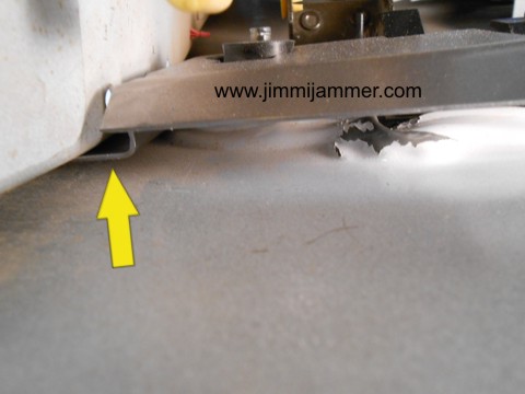
Photo 16c shows how the edge of the plate has a tab that slides into the area where the door jamb and outer door skin come together.
This acts as a second anchor point for the plate and makes the assembly very strong.
 16a (no rotary switch)
 16b (with rotary switch)
 16c
16c
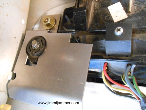
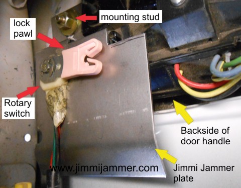
Photo 17
This shows the Jimmi' Jammer® plate in place on the drivers door. The passenger side will be very similar.
This vehicle had the rotary switch in place, so it is shown here properly installed. Vehicles without the switch will be the same, just without the switch and wires.
At this point, you can put the lock pawl back on and insert the rod in the pawl.
Test the operation of the lock using your key to make sure everything clears. If the rod rubs slightly on the plate, that is not a problem, but you can also gently bend the lock pawl outward slightly to avoid rubbing.
17 With everything in place, you are now ready to re-attach your door panel.
Photo 15
Put the splash guard back in place and reattach the bracket that holds it in place.
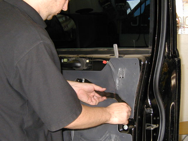
Photo 16
Set the panel back onto the door. Make sure you have reconnected any wires that were disconnected earlier, such as the lamp.
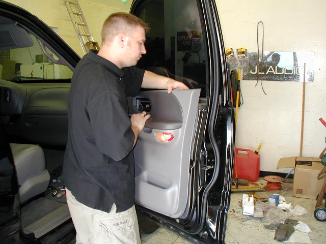
Photo 17
Put the screw that held the center of the panel in place back in place. (Reference photo 4).
Reconnect the switch and lock module connectors and snap the module back in place. Test the lock switch and window to make sure everything got connected correctly.
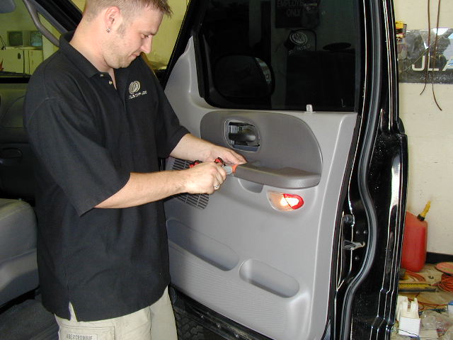
Photo 18
Reattach the handle shroud and put the remaining panel holding screws back in.
Now you can place the window warning label in the lower corner of the window. Place carefully since the adhesive on the stickers is really good.
Very Important:
Test the lock operation, window and other components one last time before starting the other door.
This completes the installation. You can put the door back together and start the other side.
All done? Check out our Gate Keeper® to prevent tailgate theft!